
5 Volt Light Box Functional Description and Connection
Wire strippers, screw driver
Tools Required
Functional Description
The 5V light box is used to verify proper part loading / clamping in a fixture. The part makes an electrical connection from 6 deck points to a common.
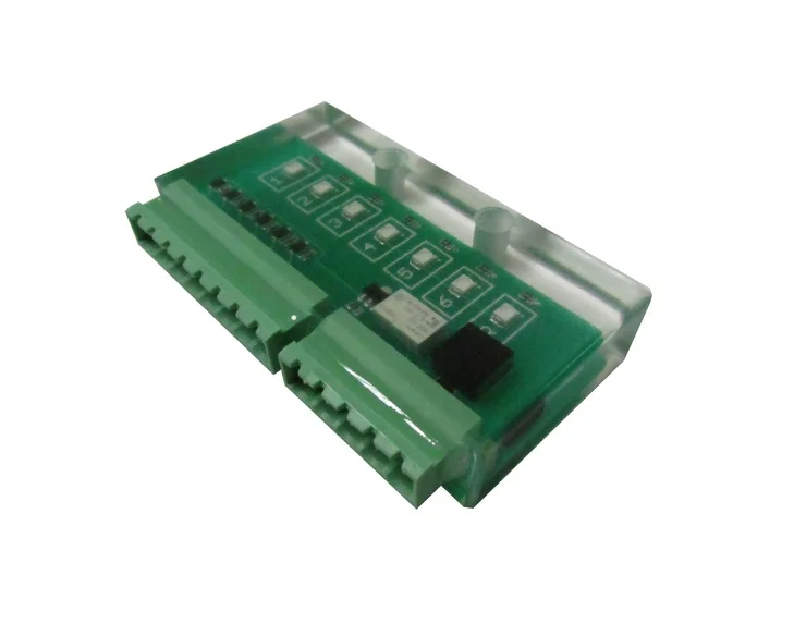
The 5V light box has two connectors. J1 and J2 J1: Is used to connect the 6 deck points and common from the fixture. J2: Is used to connect power to the light box and the relay output on the light box to the machine interface.
The light box has 7 LED's LED 1-6 are green and indicate a connection from common to deck points 1-6 LED R is blue and indicates that the output relay is energized.
The output relay on the light box is used to interface with the machine start circuitry so that the machine will not cycle unless all 6 inputs to the light box are on.
Note: All 6 green LED's must be on to energize the output relay.
Connection Description
J1 Contact connector, connector has 8 pins, labeled 1-8
- Pin 1: connect to deck point 1
- Pin 2: connect to deck point 2
- Pin 3: connect to deck point 3
- Pin 4: connect to deck point 4
- Pin 5: connect to deck point 5
- Pin 6: connect to deck point 6
- Pin 7: common, connect to the part being clamped
- Pin 8: no connection
J2 Interface connector, connector has 5 pins, labeled 1-5
- Pin 1: connect to +5VDC from machine
- Pin 2: connect to 5V common from machine
- Pin 3: return path connection point
- Pin 4: output relay NO contact
- Pin 5: output relay COM contact
Note: The connection between each deck point and common needs to be 170 ohms or less for the light box to work properly. A higher resistance will cause a dim green LED and will not energize the output relay.